Connecting to the ECU
Contents
ECU Information
Initial reverse engineering efforts occurred on a remanufactured ECU.
The ECU used for reverse engineering on the test bench is a John Deere part number SE502849 Level 11 ECU.
The block diagram for our setup can be found below:
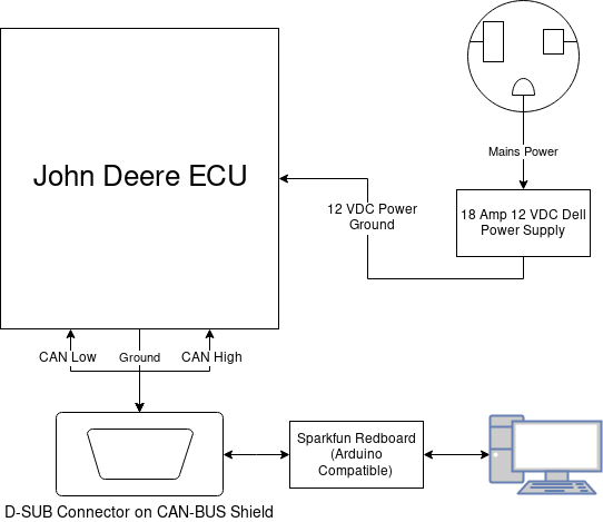
More info on the ECU internals can be found here.
ECU Pin Out
The ECU has a pinout per the table below:
| Pin Location | Usage | Typical Value | Units |
|---|---|---|---|
| B1, B2, E3 | Power | 12 | Volts DC |
| B1, B2, E3 | Power | At least 10 | Amps |
| C3, C2 | Ground | Ground | |
| L1 | CAN High | ||
| L2 | CAN Low |
The ECU connectors are left to right resting on a table with the lid off as shown in the image below:
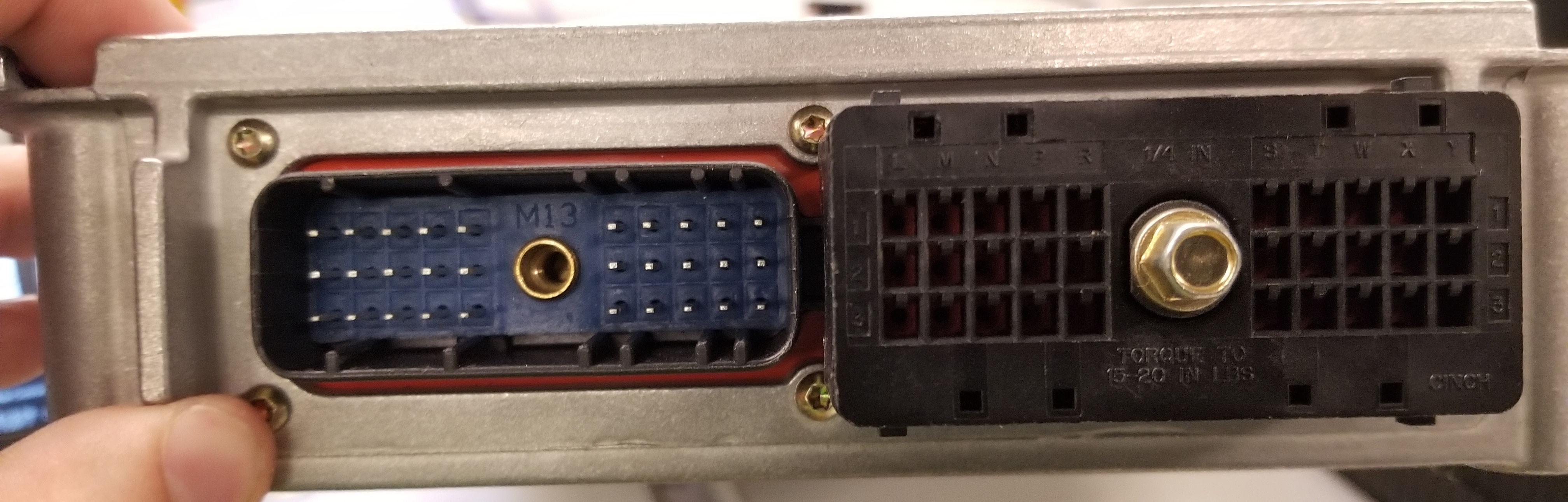
[Connector 1][Connector 2]
Connector 1 is indexed with letters A-K for columns and rows 1-3
Connector 2 is indexed with letters L-Y for columns and rows 1-3
ECU Connector
The ECU connector plug has been identified conclusively as a Cinch Connector Model 581-01-30-028 the corresponding port on the ECU is a Cinch Connector Model 581-01-60-001.