User Manual
This document serves as a quick start guide for those to pick up this work after we have finished ours.
Contents
- Connecting to a Tractor
- ECU Internals
- Finding SAE Documents
- Using the Filtering Scripts
- Using the GitHub Pages Website
Connecting to a Tractor
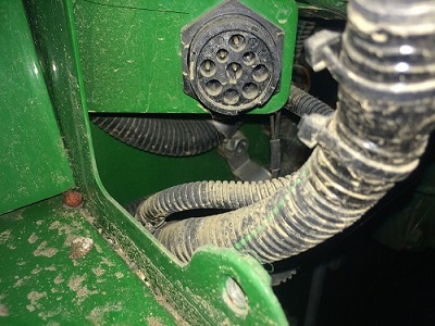
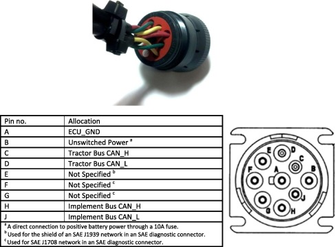
Most automobiles have an OBD-II port, which is a standard rectangular connector and communication protocol that allows users to tap into their car’s communication. The simpler John Deere tractors do not have this port, but they have something similar. It is a circular port that exposes the CAN high and low wires, as well as ground and a few other signals that aren’t needed for this project. Below are images of the connector on the John Deere 5055E tractor, and its associated pin diagram.

CAN connector on the John Deere 5055E tractor.

Pinout of the cable used to connect the scope probes to the tractor.
The cable used to connect to this port on the tractor was supplied by iFixit. It features the circular attachment needed to connect to the tractor, and a rectangular connector on the other side, that looks similar to an automotive OBD-II port but with different dimensions. Each pin on this connector is easy to read with scope probes, which is the main reason why this was used in the first place. Unfortunately there was no documentation on the pinout of the rectangular connector, so we used trial and error to identify the CAN high, low, and ground connections on this attachment. The image below shows a picture of the rectangular connector and our deduced pinout.

The annotated connector, showing the CANH, CANL, and ground.
To gather and decode the CAN packets, an oscilloscope was used to display and save everything. The scope used for this project is a Keysight MSO-X 2012A InfiniiVision Oscilloscope, with the serial decoding license installed. This product is available through the Cal Poly electrical engineering equipment checkout window.
If you are using the previously mentioned scope for this, it is simple to display the feed of CAN data on the screen. Although CAN uses two wires for communication, the scope only needs CANH to decode the packets. Connect port 1 of the scope to the CANH pin shown in the picture above, and connect scope ground to tractor ground.
If you turn on the tractor, you will see a live feed of the CANH line, alternating between 2.5V and 5V to indicate zeroes and ones. To instruct the scope to identify this as CAN data, press the ‘Serial’ key on the right side of the scope. Using the front softkeys, change the ‘Mode’ to ‘CAN’. Select ‘Signals’, and change the baud rate to 250Kb/s. Return to the previous window. Press the ‘Lister’ button, which will bring up a grid that displays a live feed of the CAN data, broken down into its ID, data, and other components.
ECU Internals
Finding SAE Documents
The Society of Automotive Engineers (SAE) sets standards for much of the electronic communication that goes on inside any automobile, and tractors are no exception. In this project, we have used SAE documentation to learn about automobile communications networks and to understand what the individual CAN messages mean. Unfortunately, SAE documents are not free, and we were only able to gather them through Cal Poly’s subscription to the SAE database. Because of this, we cannot freely post these to this website, because they are not public use. If you are a current Cal Poly student, or have access to this database through other means, then you will be able to use the same resources we did. The documents that were of the most help to us are:
- Serial Control and Communications Heavy Duty Vehicle Network - Top Level Document
- Briefly describes commonly used terms with CAN J1939 message format
- Details how an ECU usually processes and validates incoming messages
- Vehicle Application Layer - J1939-71
- Applying the J1939 standards directly to the vehicle on a low level
- This won’t be very useful when starting out, but if more progress is made this document would be useful if one is trying to control specific tractor functions
- Digital Annex of Serial Control and Communication
- The most used document, this is what is used to map specific PGN numbers to the attributes they carry
- The document cannot be posted in its entirety, but an abridged version saved as a .csv is posted in the scripts repository here
If you are a current Cal Poly student, sign in to your Cal Poly Portal and follow this link to the SAE database:
Using the Filtering Scripts
Initially, we decided to make a quick script to look through the files gathered from the tractor and look for certain CAN IDs, especially ones that appear frequently. This script kept growing in functionality as more features were needed. This is going to be a useful piece of software: although there are existing programs that already parse live CAN data (such as python-OBD, we needed one that would give us information about the data we saved. The final script and information about how to use it can be found on our pubic repository linked below.
Using the GitHub Pages Website
This website is based on GitHub Pages and Jekyll a Ruby flat-file site generator. Documentation for Jekyll can be found here and GitHub pages documentation can be found here. The site’s README.md has further notes and information on site layout and functions.
Compiling on Third Party Build Servers
The site is set up to be compiled easily on third party build servers, an example deployment pipeline can be found in the project’s Jenkinsfile.