Connecting to a Live System
Contents
- Model Information
- Scanning Session 1 - 2018-01-26
- Scanning Session 2 - 2018-01-31
- Scanning Session 3 - 2018-02-08
- Scanning Session 4 - 2018-02-15
Model Information
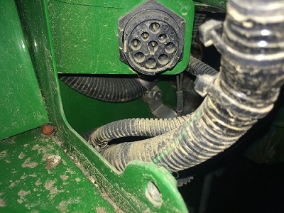
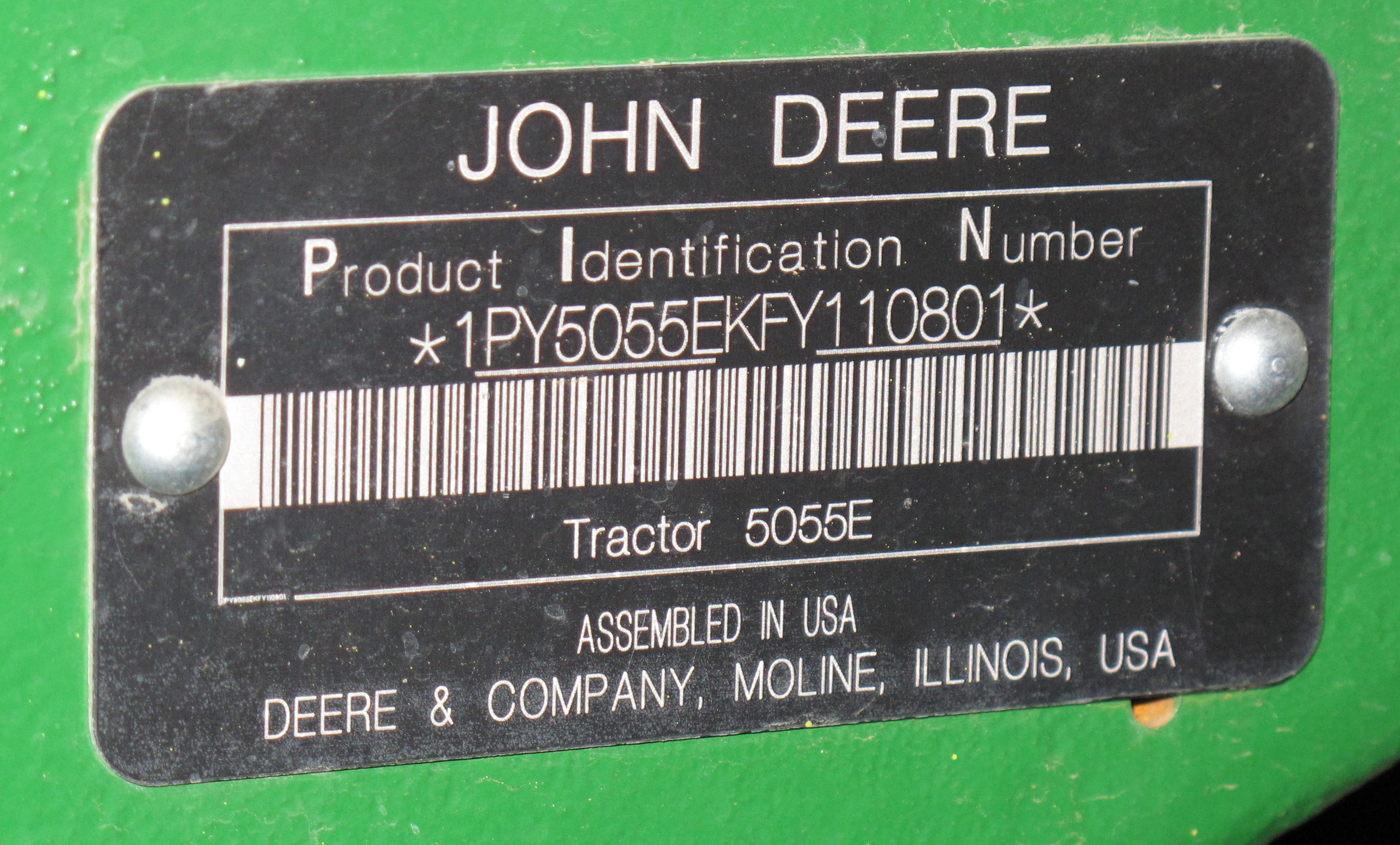
The tractor we connected to was a John Deere model 5055E. We found a CAN-BUS port to the bottom right from the driver’s point of view - a picture of it is below.
Scanning Session 1 - 2018-01-26
For the first session, we used a Sigilent 1202XE to connect to the two CAN pins that corresponded to the Tractor’s bus. After fiddling around with the scope’s settings for a bit, we got a readable signal off of a 250 kilobit scan rate - failing to match this got us garbage data. However, while our scope was able to read the signals moment-to-moment, we were not able to save this in its entirety for later processing - we took a few photos of the screen’s readout, but this was only a droplet of the data that passed through the scope. Attempting to save the capture resulted in merely 1.4 seconds of data being stored in a massive .25 GB csv file, all of which were momentary voltage readings, and it took several minutes to complete.
Scanning Session 2 - 2018-01-31
We realized that we needed a better oscilloscope if we were going to get any useful data from this. Ideally we would want a scope that can not only display the live feed of decoded CAN packets, but also one that can save the decoded can packets into a .csv file for later analysis. We found a scope that Cal Poly’s Electrical Engineering Department was willing to loan to us for our project. This scope is a Keysight Infiniivision MSOX2012A, with the serial decoding license purchased.
The second session was intended to get used to using this new Keysight scope while also obtaining some preliminary data. The group performed eight tests, making the tractor use its different functions while recording the chatter on the CAN bus. The eight tests performed were: the ignition sequence, idling with low throttle, idling with high throttle, sitting in accessory mode with no other functions activated, and the left turn signal, right turn signal, headlights, and hazards toggled all also in accessory mode. The raw data can be found on our raw data GitHub repo.
Insights
This second session gave us good insight into the computer structure of the Tractor System. We had noticed that some specific IDs attached to the messages appeared more often than others. More interestingly, some of them were very talkative when the engine was turned on, but did not appear when the tractor was in accessory mode. The two IDs of interest are 0CF00300 and 0CF00400. Some research led us to the work done by the University of Nebrasksa at Lincoln’s Biological Systems Engineering department, and a paper written by Samuel E. Marx1. This paper documented their approach at aquiring data from John Deere farm equipment for determining fuel flow rate.
Although the paper written by Marx does not focus on the architecture of the computer system like our project does, it makes some interesting points. He did mention that on his tractor, the CAN format followed a standard set by the Society of Automotive Engineers (SAE) called the J1939 protocol. The J1939 protocol sets requirements for what some specific CAN IDs must refer to. We realized that if Marx’s tractor followed this protocol, then it is very likely that ours does as well. SAE offers the documentation on its website, sae.org, but the files are hidden behind a paywall. Thankfully Cal Poly’s library offers access to this database as part of our student service, but if an ourtside user would like to access this data then they may have to pay for it themselves.
SAE offers a lookup table for the J1939 protocol CAN IDs, including the expected type of data being sent in each id, and what attribute each byte in the data packet represents. This is incredibly helpful for our causes. It allows us to focus on what types of messages make the tractor go wrong, rather than trying to decode a brand new protocol that John Deere created themselves. To confirm that this protocol carries over, we checked the messages send in this second data gathering session with the lookup table and verified that everything made sense. For example, the fourth and fifth data bytes of a message sent through the 0CF00400 ID is supposed to contain engine speed data. We had noted down what the enginer RPM was when the tractor was idling at low vs. high throttle, roughly 950 RPM vs. 1300 RPM. These bytes, along with all others we tested, matched the documentation, indicating that this tractor was as well using the SAE J1939 protocol.
Scanning Session 3 - 2018-02-08
The third session allowed us to collect roughly 25 times the data of any previous session via the Segmented Capture feature of the Keysight scope. This allowed capture of just short of 10 seconds of data from data capture start to end, significantly more than the 200ms from the previous session. Testing setup remained the same from session one besides the scope configuration change. The raw data can be found on our raw data GitHub repo.
Insights
Data is still being analyzed.
Scanning Session 4 - 2018-02-15
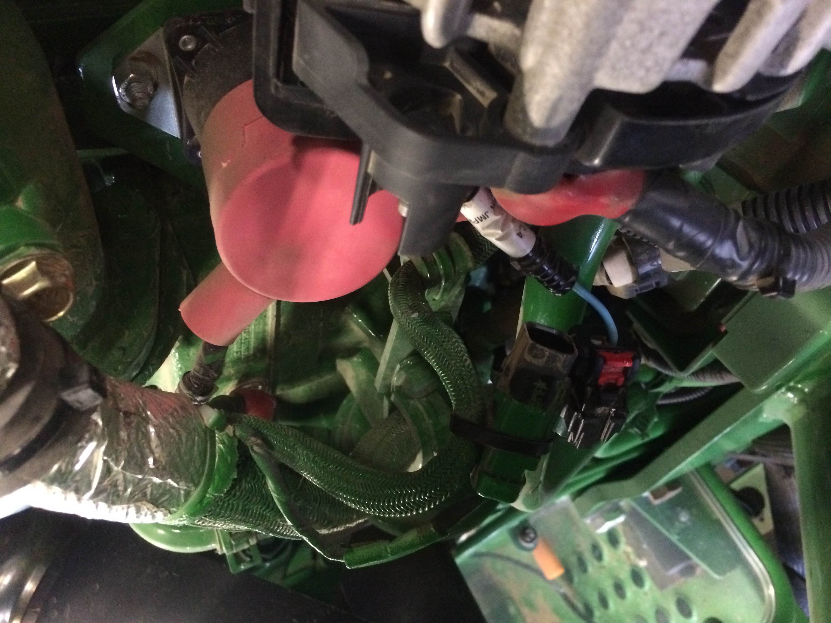
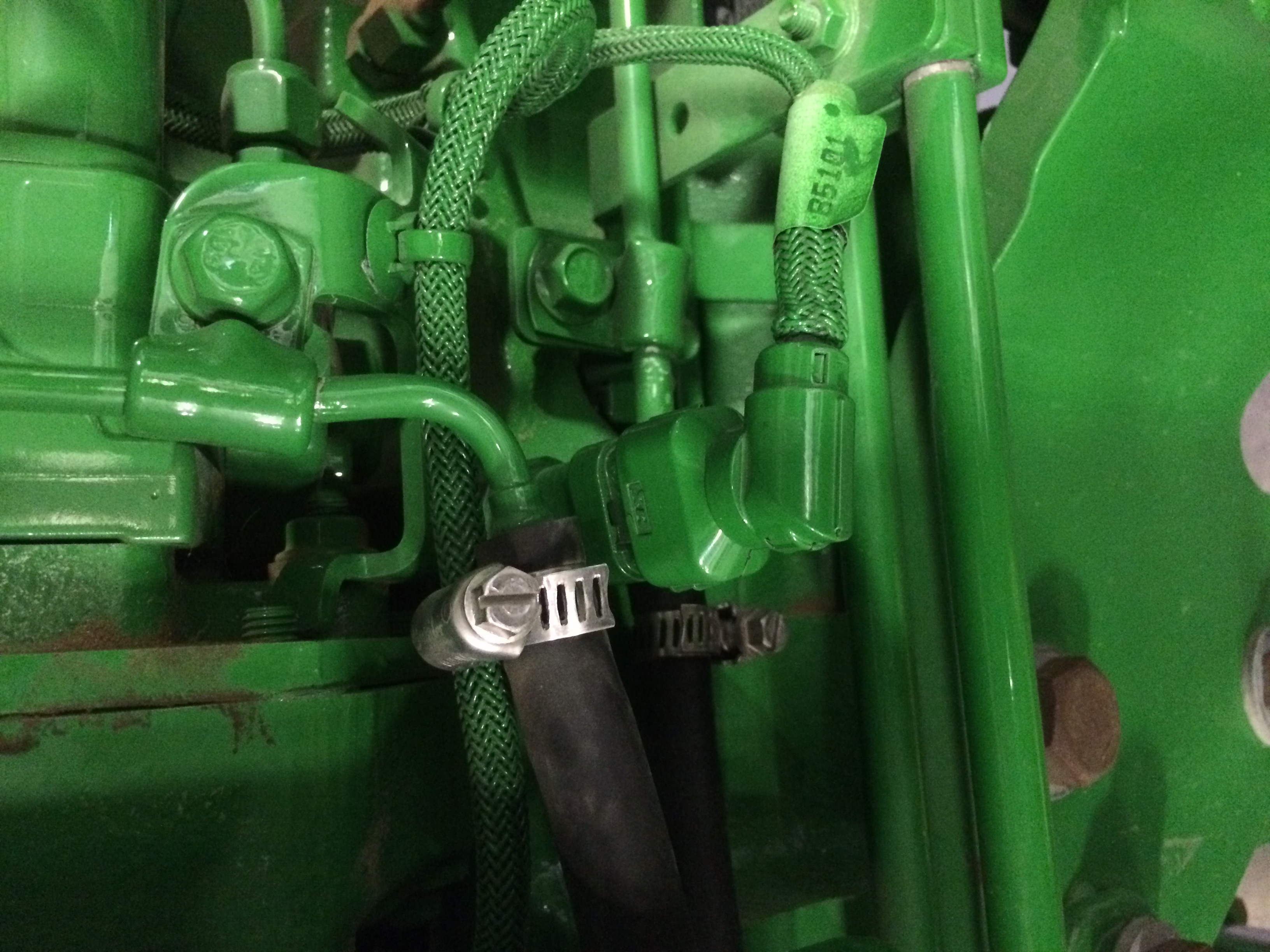
In this scanning session we disconnected a variety of sensors in order to check what John Deere’s error codes appear as on the CAN network.
The three disconnected sensors can be shown in images below:
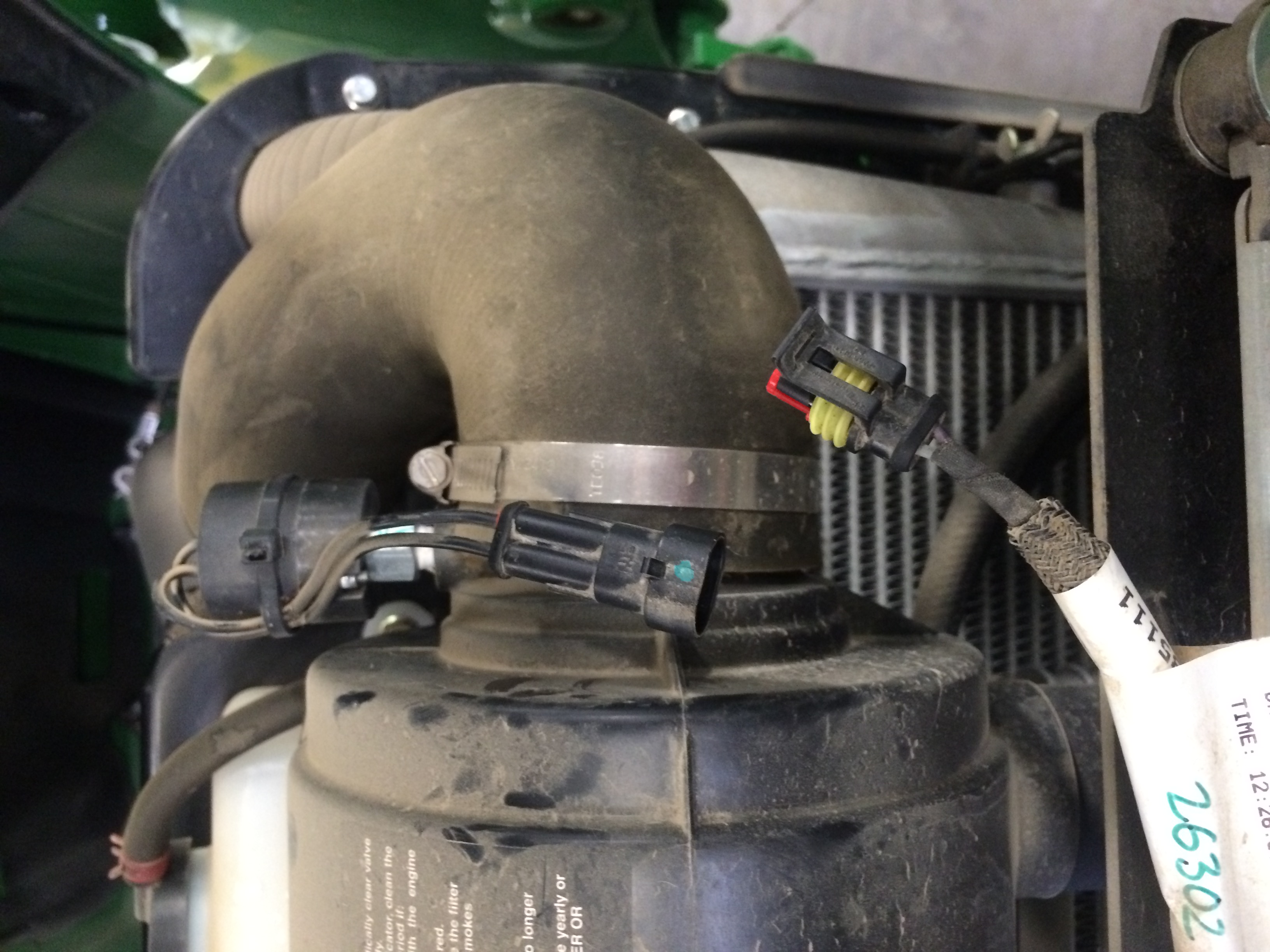
The raw data can be found on our raw data GitHub repo.
Insights
Data is still being analyzed.